$C000-$CFFF
Most major screen editor routines can, and should, be entered through their respective entries in the following jump table. Each three-byte table entry consists of a JMP opcode followed by the address of the target routine.
49152 $C000 JCINT
Entry point for the routine at 49275/$C07B which establishes the default characteristics for both the 40- and 80-column displays. This entry is part of both the reset and RUN/STOP RESTORE sequences. No preliminary setup is required, but the behavior of the routine is affected by the setting of the initialization status flag ($0A04). The keyboard decoding table pointers and screen editor indirect vectors are initialized only when bit 6 of the flag is %0. If you wish to preserve decoding table pointers or indirect vectors while resetting other screen editor characteristics, set this bit to %1 before you call the routine.
49155 $C003 JDISPLY
Entry point for the routine at 52276/$CC34, which deposits a screen code and attribute value at the current cursor position. Call this entry with the accumulator holding the screen code (not the character code) for the desired character and the X register holding the attribute value for the character.
49158 $C006 JKEYIN
Entry point for the routine at 49716/$C234, which retrieves a single character from the keyboard. In official Commodore literature, this routine has the rather nondescriptive name LP2. This entry is used by the Kernal GETIN routine $EEEB when the keyboard is the input device. (The keyboard, device 0, is the 128’s default input device.) Upon return, the accumulator will contain the retrieved character. Be sure to see the warning in the KEYIN entry about calling this routine directly.
49161 $C009 JGETSCRN
Entry point for the routine at 49819/$C29B, which retrieves a character from a line of keyboard or screen input. In official Commodore literature, this routine has the rather nondescriptive name LOOP5. This entry is used by the Kernal BASIN routine $EF06 when input is requested from the keyboard (device 0) or the screen (device 3). The input source is determined by the value in the flag at 214/$D6. When the flag has a nonzero value, the character at the current cursor position is read and returned in the accumulator. When the end of the line of input is reached, the routine returns the code for the RETURN character, the value 13/$0D. If the flag is zero, the routine accepts characters from the keyboard and displays them on the screen until RETURN is pressed. It then returns the first character of the input in the accumulator and sets the source flag to a nonzero value so that subsequent calls retrieve characters from the input line displayed on the screen. In either case, the source flag should be set only before the first call to this routine for any given line of input.
For keyboard input, the starting and ending columns and the row for the input line are set automatically. For screen input, the character is read from the row specified in 235/$EB at the column specified in 236/$EC. These locations normally hold the current cursor position and are advanced one position to the right after each call to this routine. However, the locations can also be reset to any row and column you desire. The screen input line ends on the row specified in 2608/$0A30 at the column specified in 234/$EA. Neither of these locations is set automatically, so you must specify the ending position before calling for input from the screen. The X and Y register contents will be preserved during this routine.
49164 $C00C JPRINT
Entry point for the routine at 50989/$C72D, which prints a character at the current cursor position using the current attribute (in 241/$F1). This routine is used by the Kernal BSOUT routine $EF79 when the screen is specified as the output device. The screen, device 3, is the 128’s default output device. Call the entry with the accumulator containing the character code (not the screen code) for the character to be displayed. The accumulator and X and Y register contents are preserved during this routine.
49167 $C00F JSCRORG
Entry point for the routine at 52315/$CC5B, which returns information about the current window size. This entry is the target of the Kernal jump table entry SCRORG [$FFED], Upon return, the X register will hold the number of columns (minus 1) in the current window, and the Y register will hold the number of rows (minus 1). The accumulator will hold the maximum column number for the active screen (39 for the 40- column display or 79 for the 80-column display).
49170 $C012 JSCNKEY
Entry point for the routine at 50525/$C55D, which scans the keyboard matrix for a keypress. This entry is the target of the Kernal jump table entry SCNKEY $FF9F. If a key is found to be pressed, its corresponding character code will be placed in the keyboard buffer for retrieval by the GETIN or BASIN routines, unless the key is a shift key or programmable key. Both of those get special handling (see the SCNKEY routine for details).
49173 $C015 JREPEAT
Entry point for the routine at 50769/$C651, actually an alternative entry into the SCNKEY routine. At this point, the routine expects location 212/$D4 to contain the keyscan matrix code for the current key, 211/$D3 to hold the status of the shift keys, and 204-205/$CC-$CD to point to the keyboard decoding table selected according to the shift key status. This table entry is most useful when intercepting the KEYVEC indirect vector (see the entry at 826/$033A for details).
49176 $C018 JPLOT
Entry point for the routine at 52330/$CC6A, which reads or sets the cursor position. This entry is the target of the Kernal jump table entry PLOT $FFF0, If called with the carry bit clear, the cursor is moved to the row specified in the X register and the column specified in the Y register (the row and column settings are relative to the current home position of the window). The carry bit will be set upon return if the specified position is outside the current window boundaries. If called with the carry set, the routine returns with the row number of the current cursor position in the X register and the column number in the Y register (again, the numbers will be relative to the current home position of the window).
49179 $C01B JCRSR80
Entry point for the routine at 52567/$CD57, which moves the cursor on the 80-column display to the row and column specified in 235/$EB and 236/$EC, respectively. The 40-column display’s cursor is maintained by software, so it follows these pointers automatically, but the position of the 80-column cursor must be set explicitly.
49182 $C01E JESCAPE
Direct entry point into the escape sequence handling routine [$C9BE], Normal entry into the handler begins with an indirect jump through the ESCVEC vector (824-825/$0338-$0339). That vector normally points to this table entry, which in turn jumps back into the handling routine at the point immediately following the indirect jump.
49185 $C021 JKEYSET
Entry point for the routine at 52386/$CCA2, which redefines a programmable key. This entry is the target of the Kernal jump table entry PFKEY [$FF65]. Call this entry with the X register containing the key number (1-10), the Y register containing the length of the definition string, and the accumulator holding the address of a two-byte zero-page pointer to the string. The zero-page byte immediately following the pointer should contain the number of the memory bank in which the string resides.
49188 $C024 JSCNIRQ
Entry point for the routine at 49556/$C194, which handles the screen editor portion of the IRQ handling sequence. This includes setting up the screen display mode, scanning the keyboard, and managing the cursor for 40-column display.
49191 $C027 JINIT80
Entry point for the routine at 52748/$CE0C, which initializes the character patterns for the 80-column display. This entry is the target of the Kernal jump table entry INIT80 [$FF62]. The routine copies the contents of the 40-column display’s character ROM ($D000-$DFFF in bank 14) into the character definition area of the 8563 chip’s private block of RAM.
49194 $C02A JSWAPPER
Entry point for the routine at 52526/$CD2E, which switches active screen displays. This entry is the target of the Kernal jump table entry SWAPPER $FF5F. The routine exchanges the screen variable tables, tab stop tables, and line link tables, and toggles the active screen flag (215/$D7). This will redirect printing to whichever screen was previously inactive.
49197 $C02D JWINDOW
Entry point for the routine at 51739/$CA1B, which sets the position of a corner of the output window. To set the top row and left column of the window, call this entry with the carry bit clear, the accumulator holding the row number, and the X register holding the column number. To set the bottom row and right column of the window, call this entry with the carry bit set, the accumulator holding the row number, and the X register holding the column number.
49200 $C030 Unused
Three unused bytes filled with the value 255/$FF.
49203 $C033 SADDRTBL
Table of screen line starting addresses
Locations 49203-49227/$C033-$C04B hold the low bytes of the address in 40-column screen memory for the column 0 position in each of the 25 screen lines. Locations 49228-49252/$C04C-$C064 hold the high bytes for the line addresses for the default 40-column screen position (at 1024/$0400). These table values are used in conjunction with the screen base addresses, 2619/$0A3B for the 40-column screen or $2606/$0A2E for the 80-column screen, to calculate the actual starting address for each line of screen and attribute memory.
49253 $C065 SCNVCTRS
Table of default screen editor indirect vectors
The five two-byte values here are copied to the screen editor indirect vector table at 820-829/$0334-$033D when the system is reset. In each case, the default indirect vector merely returns control to the location immediately following the indirect jump,
49263 $C06F KEYPTRS
Table of default keyboard decoding table pointers
The six two-byte values here, the addresses of the ROM keyboard decoding tables, are copied to the keyboard decode pointer table at 830-841/$033E-$0349 when the system is reset.
49275 $C07B CINT
Initializes screen editor constants, variables, tables, and vectors
This routine has a screen editor jump table entry at 49152/$C000 and a Kernal jump table entty at 65409/$FF81. Sets the default values for all working storage memory locations used by screen editor routines. This routine is part of both the reset and RUN/STOP-RESTORE sequences. The CIA chip register (56576/$DD00) that controls VIC-II chip memory banking is set to have the VIC-II see memory from its bank 0, corresponding to addresses 0-16383/$0000-$3FFF in block 0 of system RAM (VIC-II banks are different from MMU banks; see Chapter 8 for more details). Bit 1 of the processor I/O register (1/$01) is set to %1 to make block 1 of color memory (the block for 40-column text screen color) visible at 55296/$D800. The Kernal CLRCH routine $FFCC is called to reset normal I/O sources: input from the keyboard and output to the screen. The SID chip volume register (54296/$D418) is set to zero to silence any sound output (a step not present in the Commodore 64’s CINT routine). Screen editor RAM variables and constants are initialized as follows:
| Location | Value | Meaning |
|---|---|---|
| 208/$D0 | 0 | Keyboard buffer empty |
| 209/$D1 | 0 | No function key pending |
| 214/$D6 | 0 | Input from the keyboard |
| 216/$D8 | 0 | 40-column display set for text mode |
| 217/$D9 | 0 | CHAREN shadow cleared |
| 2592/$0A20 | 10/$0A | Maximum of 10 keys in buffer |
| 2593/$0A21 | 0 | Printing pause flag cleared |
| 2594/$0A22 | 128/$80 | All keys repeat if held down |
| 2595/$0A23 | 4/$04 | Delay between repeats initialized |
| 2596/$0A24 | 10/$0A | Delay before repeats initialized |
| 2598/$0A26 | 0 | 40-column cursor will blink |
| 2599/$0A27 | 10/$0A | Cursor blink switch initialized |
| 2600/$0A28 | 10/$0A | Cursor blink countdown initialized |
| 2603/$0A2B | 96/$60 | 80-column cursor set for blinking block |
| 2604/$0A2C | 20/$14 | 40-column text screen and character base initialized (screen at 1024/$0400, character set seen at 4096/$1000) |
| 2605/$0A2D | 120/$78 | 40-column bitmap and matrix base initialized (matrix at 7168/$1C00, bitmap at 8192/$2000) |
| 2606/$0A2E | 0 | Base page for screen memory in 8563 RAM (screen at 0/$0000) |
| 2607/$0A2F | 8/$08 | Base page for attribute memory in 8563 RAM (attributes begin at 2048/$0800) |
| 2612/$0A34 | 208/$D0 | Default raster line for split screen (text portion starts at line 20) |
| 2619/$0A3B | 4/$04 | Base page for 40-column screen memory (value read from 49228/$C04C) |
Also during this setup, the active screen flag (215/$D7) is set for 40-column mode, and bit 7 of the MMU mode configuration register (54533/$D505) is set to %1 to enable reading of the 40/80 DISPLAY key. While the 40-column display is active, default tab stops are set and default screen editor variables are copied from the table at 52852/$CE74 into 224-249/$E0-$F9. At the same time, default variables for the 80-column display are copied from the table at 52878/$CE8E into 2624-2649/$0A40-$0A59. However, there is a bug in this portion of the routine: The copy loop uses an index of 26/$1A instead of the proper value 25/$19, so the byte following the 40-column table is also copied to 250/$FA, and the byte following the 80-column table is also copied to 2650/$0A5A. The screen editor indirect vectors (820-829/$0334-$033D) are initialized from the table at 49253/$C065.
Next, bit 6 of the initialization status flag ($0A04) is checked. If the bit is set to %1 , the following steps to load keyboard table pointers and key definition strings are skipped. If the bit is clear, the keyboard decoding table pointers (830-841/$033E-$0349) are initialized from the table at 4926/$C06F, and the default programmable key definitions are copied to the definition area at 4096/$1000 from the table at 52904/$CEA8. After the values are copied, bit 6 of the flag is set to %1 to indicate that these steps have been performed. The flag is cleared before this routine is called by the reset routine $E000, so these steps will always be performed during a reset. However, the RUN/STOP-RESTORE sequence $FA53 does not affect the flag, so any changes to programmable key definitions or keyboard decoding table pointers will remain intact after RUN/STOP-RESTORE.
Default tab stops are then established for the 80-column screen, and the 80-column window is reset to full screen size and cleared. The 40-column window is also reset to full screen size and cleared. Finally, the position of the 40/80 DISPLAY key is read (by checking bit 7 of 54533/$D505), and the selected display will become the active screen upon exit.
49474 $C142 CLEAR
Clears the current window and homes the cursor
Also handles clear screen character, CHR$(147). Sets the cursor to the home position and clears rows until the bottom of the window is reached, then falls through into the following routines to return the cursor to the home position and set pointers.
49488 $C150 HOME
Moves the cursor to the home position of the current window
Sets the cursor row (235/$EB) and starting row for input (232/$E8) to the top row of the current window (229/$E5), and the cursor column (236/$EC) and starting column for input (233/$E9) to the left margin of the current window (230/$E6), then falls through into the next routine to set pointers to that line.
49500 $C15C SETLINE
Sets starting address pointers for the current line
Loads the line number where the cursor currently resides (235/$EB) into the X register, then falls through into the next routine to set pointers to that line.
49502 $C15E SETADDR
Sets starting address pointers for a specified line
Calculates the screen memory address corresponding to the leftmost column of the screen line specified in the X register and places the address in the pointer at 224-225/$E0-$E1. The low byte of the address comes from the table at 49203/$C033 (multiplied by 2 if the 80-column display is active). The high byte is calculated by taking a value from the table at 49228/$C04C, masking off all but the lowest two bits (and multiplying the result by 2 if the 80-column screen is active), then ORing the result with the starring page value for the active screen 2619/$0A3B for the 40-column display or 2606/$0A2E for the 80-column display.
Next (at 49532/$C17C), the attribute memory address corresponding to the leftmost column of the specified screen line is calculated and placed in the pointer at 226-227/$E2-$E3. The low byte of the address is taken directly from the low byte of the screen memory pointer (224/$E0). For the 40-column screen, the high byte is calculated by masking off all but the lowest two bits of the screen memory pointer high byte (225/$E1), then ORing the result with the value 216/$E8216/$D8 (40-column color memory always starts at $D800). For the 80-column screen, the high byte is calculated by masking off all but the lowest three bits of the screen memory pointer high byte (225/$E1), then ORing the result with the attribute memory starting page value (2607/$0A2F).
49556 $C194 SCNIRQ
Performs screen and keyboard portion of IRQ functions
This routine has a jump table entry at 49188/$C024. Begins by checking whether the current IRQ is the result of a raster interrupt. If it’s not, then this can’t be a normal jiffy IRQ, so the routine skips the screen setup steps and just scans the keyboard and blinks the cursor before exiting. If it is a raster interrupt, the routine checks whether the screen mode flag (216/$D8) contains the value 255/$FF. If so, the routine again skips ahead to scan the keyboard, blink the cursor, and exit. The 128 itself never puts that value into the flag, but you can use this feature when you set up your own custom screen mode or raster interrupt (see the entry for location 216/$D8 for details).
The routine then checks whether the raster is currently on scan line 256 or higher. If so, the interrupt occurred while the raster was beyond the visible portion of the screen. This offscreen raster interrupt is the normal jiffy IRQ source for the 128-quite a different technique from the CIA timer-driven jiffy IRQ for the Commodore 64. The interrupt is actually triggered at line 255, but the raster will have moved to the next scan line by the time its position is checked here. For an offscreen interrupt, the VIC-II chip registers will be set according to the screen mode flag value, using the step at 49631/$C1DF for mode 0 (a full text screen) or the one at 49587/$C1B3 for a bitmapped or split-screen mode.
If the interrupt occurred above scan line 255, bit 6 of the screen mode flag is tested. If that bit is set to %1 , a split screen mode is in use, so a branch is taken to 49631/$C1DF to set VIC-II registers for the text portion of the display. Otherwise, the registers are merely reset for whichever mode is currently in use, which produces no obvious effect.
At 49587/$C1B3, the bitmapped or multicolor bitmapped screen is established. If a split screen is in use, the scan line value for the split, stored in 2612/$0A34, is loaded into the VIC-II’s raster compare register (53266/$D012). The processor I/O register (1/$01) is set to make block 0 of color memory- the block for multicolor source 3-visible at 55296/$D800, and the VIC memory control register (53272/$D018) is loaded with the bitmap base address, stored in 2605/$0A2D. Bit 5 of VIC control register 1 (53265/$D011) is set to %1 to enable the bitmapped display. If the mode flag indicates that multicolor bitmapped mode was selected, bit 4 of VIC control register 2 (53270/$D016) is also set to %1 to enable that feature.
At 49631/$C1DF, the 40-column text screen (or the text area of a split screen) is established. The VIC-II’s raster compare register (53266/$D012) is loaded with 255/$FF to trigger the offscreen raster interrupt. The processor I/O register (1/$01) is set to make block 1 of color memory-the block for 40-column text color-visible at 55296/$D800, and the VIC memory control register (53272/$D018) is loaded with the screen and character memory base value, stored in $2604/$0A2C. The VIC control register bits for bitmapped and multicolor are cleared to disable those display modes. Finally, a short delay loop is executed if the text portion of a split screen is being established. This is to insure that the switch from bitmapped to text modes occurs while the raster is off the right edge of the visible screen area, which prevents the flicker that would occur if the change occurred in the middle of scanning a line.
If the IRQ source is a raster interrupt which occurred on the visible screen (to set up the text portion of a split screen), the routine exits at this point with the status register carry bit clear. In all other cases, the routines to scan the keyboard for a keypress $C55D and handle 40-column cursor blinking $C6E7 are called, and the carry bit will be set upon exit.
49716 $C234 KEYIN
Performs GETIN from keyboard
This routine has a jump table entry at 49158/$C006. Checks 209/$D1 to see whether any characters remain to be read from the definition string for the most recently pressed programmable key. If so, a character is read from the definition area, with the value in 210/$D2 used as an offset from the start of the definition area (4106/$100A). The count of remaining characters is decremented and the offset into the definition area is incremented; then the routine exits with the character in the accumulator, the status register carry bit clear, and IRQ interrupts reenabled.
If no programmable key string characters are pending, the character at location 842/$034A, the first character in the keyboard buffer, is returned in the accumulator. Any remaining characters in the buffer are shifted one position to the left to remove the retrieved character from the buffer; then the count of characters in the buffer (208/$D0) is decremented. Upon exit, the status register carry bit will be clear and IRQ interrupts will be reenabled.
Unlike other major screen editor routines with jump table entries, you should avoid calling this one directly. To retrieve keypresses, call the Kernal GETIN routine via its jump table entry (65508/$FFE4) with the current input device (153/$99) set to zero to indicate keyboard input. The Kernal GETIN routine $EEEB verifies that a character is waiting to be read from either a programmable key string or the keyboard buffer before it calls this routine. If you call this routine with no characters available (with 208/$D0 and 209/$D1 both containing zero), you’ll cause serious problems. The contents of all page 3 locations above the keyboard buffer (and part of 40- column screen memory in page 4) will be garbled. This area includes the vital indirect fetch and store routines; you’ll have to reset the computer to recover.
49752 $C258 KEYLIN
Accepts a line of keyboard input and returns the first character
The normal entry point for this routine is 49755/$C25B. Turns on the cursor, then waits until a character is available in the keyboard buffer or from a programmable key definition string. The routine above is called to retrieve the character, and unless it’s a RETURN character, code 13/$0D, the routine loops to display the character on the screen at the current cursor position (using the PRINT routine $C72D), move the cursor to the next position, and wait for another character to become available. When RETURN is encountered, the routine falls out of this loop and stores the RETURN code in the input source flag (214/$D6) so that subsequent calls to the keyboard BASIN routine will retrieve characters from the line of input that has been displayed on the screen. The routine then sets pointers to the input screen line and jumps to 49852/$C2BC in the following routine to exit with the accumulator holding the first character of the input-unless no other characters were typed before RETURN, in which case the routine branches to 49829/$C2A5 in the following routine to exit with the RETURN character code in the accumulator.
49819 $C29B GETSCRN
Performs BASIN from screen or keyboard
This routine has a jump table entry at 49161/$C009. Stashes the contents of the X and Y registers on the stack for later restoration, then checks the input source flag (214/$D6). If the flag value is zero, indicating input from the keyboard, the preceding routine is used to accept a line of input from the keyboard. If the flag is nonzero, but with bit 7 clear (%0), the routine branches ahead to 49852/$C2BC to retrieve a character from a screen line. If bit 7 is set (%1), the end of the input line has been reached, so (at 49829/$C2A5) the input source flag is reset to zero and a RETURN character is printed unless output is to a device other than the screen. The routine then exits with the RETURN character code, 13/$0D, in the accumulator (the X and Y registers will be restored to their original values).
At 49852/$C2BC, the screen code at the current cursor position is retrieved and converted into the corresponding character code (disassemble $C2C2-$C2D8 to see the conversion process). The routine then checks whether the end of input has been reached. If so, bit 7 of the input flag is set to %1 to indicate that all characters have been read from the current input line.
The cursor is then moved right to the next character position in the line. If the calculated character code is 222/$DE, the pi (K) character, it’s replaced with 255/$FF, an alternative value (and BASIC token) for that character. Before exiting, the original X and Y register values placed on the stack at the start of the routine are restored, and retrieved character code is loaded into the accumulator. The status register carry bit will be clear upon exit.
Although there are no bugs in this routine, its calling Kernal routine (BASIN $EF06) will not correctly retrieve a line of input from the screen (keyboard input functions properly). The screen input setup portion of BASIN has two major flaws: It does not set the ending row for input (2608/$0A30), and it resets the input source flag (214/$D6) before each character is retrieved (so that the setting of bit 7 is lost). Together, these bugs make it impossible to determine when the end of the input is reached. The following is an example of the proper technique for retrieving a line of input from the screen:
      LDA $EB       // Set ending row for input
      STA $0A30     // (same as starting row)
      LDA $E7       // Set ending column for input
      STA $EA       // (to right window margin)
      LDA #$03      // Set screen as input source
      STA $D6       // (any nonzero value will do)
      LDX #$00      // Initialize storage offset
LOOP  JSR $C009     // Read character from the screen
      CMP #$0D      // Is it RETURN?
      BEQ EXIT      // Exit if so
      STA $0C00,X   // Stash character from screen
      INX           // increment the offset
      BNE LOOP      // Loop for another character
EXIT  RTS
49919 $C2FF QUOTECK
Handles quote mode flag
Checks whether character value in the accumulator is 34/$22, the quote (“) character. If so, bit 1 of the quote mode flag (244/$F4) is toggled, turning quote mode on if it was previously off or off if it was previously on. The character value will still be in the accumulator upon exit.
49932 $C30C PRNTEXIT
Provides common exit for screen BSOUT subroutines
Stores the current character code (239/$EF) as the previous character code (240/$F0). The subroutine to move the cursor on the 80-column screen [$CD57] is called to actually move the cursor if that display is active. This is necessary because the 80-column screen’s cursor is controlled by hardware (not by software, like the 40-column screen’s cursor), so it doesn’t automatically move when its corresponding row and column pointers are updated. The pending insert count (245/$F5) is checked. If it’s nonzero, the quote mode flag is cleared. As a result, you won’t go into quote mode if you type the quote character for a pending insert unless the quote is typed for the last insert. Before exiting, the routine reloads the accumulator and X and Y registers with the values stored on the stack when the BSOUT routine was entered $C72D, so all register values are preserved during BSOUT. The status register carry bit will be clear upon exit.
Because the address of this routine is pushed onto the stack at the start of the screen BSOUT routine $C72D, all screen printing subroutines will return to the calling routine via this routine.
49952 $C320 SETCHAR
Handles character printing for screen BSOUT
Handles all character display functions for the screen BSOUT routine $C72D, including quote, reverse, and autoinsert modes. The routine has several entry points, depending on the desired effect. For any of these entry points, the code to be printed should be in the accumulator upon entry:
49952/$C320: Entry point for printing character codes 160-254/$A0-$FE. Prior to entry, bit 7 of the code will have been cleared to %0. This step forces bit 6 to %1, so character codes 160-191/$A0-$BF become screen codes 96-127/ $60-$7F, and character codes 192-254/$C0-$FE become screen codes 64-126/$40-$7F.
49954/$C322: Entry point for printing character codes 32-127/$20-$7F. Prior to entry, the character code will have been converted to a screen code by the screen BSOUT control routine $C72D. This step checks whether reverse mode is active (indicated by a nonzero value in 243/$F3). If that mode is not active, the next step is skipped.
49958/$C326: Entry point for printing characters in reverse video; also used for character codes less than 32 and for codes 128-159 when those characters are printed in quote mode or at a pending insert. For codes 1-31/$01-$1F, the character code is used unchanged, so those characters are represented by the reverse images of screen codes 1-31/$01-$1F. For characters 128-159/$80-$9F, bit 7 will have been cleared to %0, and bit 6 set to %1 prior to entry, so those characters are represented by the reverse images of screen codes 64-95/$40-$5F.
If autoinsert mode is active (indicated by bit 7 of 246/$F6 set to %1), a space is inserted at the current cursor position before the character is printed. (The count of inserts pending is also cleared; you can’t have inserts pending in autoinsert mode.) The subroutine at 52271/$CC2F is used to place the character on the screen at the current cursor position using the current attribute value from 241/$F1; then the routine falls through into the following one to move the cursor to the next position.
49982 $C33E UDCRSR
Updates the cursor position
Compares the current cursor column (in the Y register upon entry) against the right window margin (231/$E7). If the cursor is at the right edge of the window, the routine checks whether the cursor is also already on the bottom line of the window. If so, the scrolling enable flag (248/$F8) is checked. The cursor will not be moved if scrolling is not allowed when the cursor reaches the lower right corner of the window. Otherwise, the cursor is moved right one position. If the cursor moves beyond the right window margin, a new blank line is inserted and linked to the one above, and the cursor is moved to the left margin of this new line. However, linking can be disallowed by setting bit 6 of 248/$F8 to %1. In this case, the cursor will simply wrap around to the left margin without inserting a new line. This link-disable feature is not directly supported on the 128-there’s no character or ESC sequence to disable linking-so you must set or clear the bit directly. See the entry for location 248/$F8 for details.
50019 $C363 NEXTLIN
Moves the cursor down one line
Moves the cursor down to the next row in the window. If the cursor is already on the bottom row of the window, the scrolling enable flag (248/$F8) is tested. If scrolling is allowed, the window contents are scrolled upward by one row, and the bottom row (where the cursor now resides) is cleared. If scrolling is disabled, the cursor is wrapped to the top row of the window.
50044 $C37C OPENLIN
Inserts a new line linked to the one above
Copies all lines in the window below the one on which the cursor currently resides down one row (the bottom line will be lost). The line on which the cursor resides is then cleared and linked to the one above.
50086 $C3A6 SCROLL
Scrolls the window up one line
Copies all lines in the window up one row. The top line will be lost and the bottom line will be cleared. If the new top line was originally linked to the line scrolled off the window, it will be unlinked.
50140 $C3DC SCRLUP
Copies lines up one row and clears bottom line
Copies all lines in the window below the one specified in the X register up one row. The specified line will be overwritten, and the bottom line will be cleared and unlinked. The line link bits for each line are also copied to the new positions so that the links will be maintained intact. This routine also checks column 7 of the keyboard matrix (see the entry at 50525/$C55D) to test the Commodore key. If that key is found to be pressed, a delay loop is executed. Since this is the subroutine used to open new lines at the bottom of the window while printing, this feature allows the Commodore key to slow screen scrolling. There is no simple way to defeat this feature.
50189 $C40D MOVLINE
Copies a line
Copies characters from the line specified in the X register to the one pointed to in 224-225/$E0-$E1, and copies the attributes for the line to the attribute line pointed to in 226-227/$E2-$E3. The copying begins at the column specified in the Y register and extends to the left window margin. The copy is performed on whichever display, 40- or 80-column, is currently active. The X register will still contain the source line number upon exit.
50189 $C4A5 CLRLINE
Clears a line
Writes a space character with the current attribute (from 241/$F1) at every character position between the left and right window margins of the line specified in the X register. The operation is performed on whichever display, 40- or 80-column, is currently active. The link bit for the line is also cleared, unlinking the line. Upon exit, the X register will still contain the line number and the Y register will hold the column number of the right window margin.
50492 $C53C FILLSRAM
Fills or copies a block of 8563 RAM
Uses the hardware fill/copy feature of the 8563 chip to fill or copy a block of the 8563’s private 16K of RAM. The block starts at the address currently in 8563 registers 18-19/$12-$13 and ends at the address in 2620-2621/$0A3C-$0A3D. The operation is determined by the state of bit 7 of 8563 register 24/$18. If the bit is %0, the block is filled with the value in 8563 register 31/$1F. If the bit is %1, the contents of locations starting at the address in registers 32-33/$20-$21 are copied to the block.
50525 $C55D SCNKEY
Scans keyboard matrix for keypress
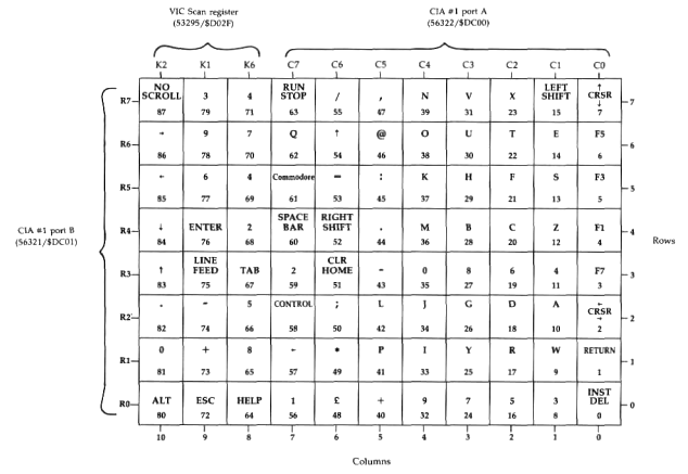
(This routine has a screen editor jump table entry at 49170/$C012 and a Kernal jump table entry at 65439/$FF9F.) Begins by checking bit 6 of location l/$01 to determine the position of the CAPS LOCK key. If that key is down, the shift key flag (211/$D3) will be set to 16/$10 (bit 4 set to %1); otherwise, it will be cleared to zero. Next, the keyscan code (212/$D4) is initialized to 88/$58, the value for no key pressed. The keyboard matrix is checked to see whether any keys are pressed. If not, the routine jumps to 50839/$C697 in the next routine to set 88 as the matrix code value. If a key has been pressed, the routine loads the keyboard decode table pointer (204-205/$CC-$CD) from 830-831/$033E-$033F, which holds the address of the default table, and begins the process of determining which key is being pressed. The keyboard is arranged electrically as a matrix of 11 columns and eight rows (next figure). To scan for a keypress, the CIA or VIC port bit for one of the 11 columns is set to %0, while the bits for all other columns are held at %1 . While the column bit is %0, the CIA port for the eight rows (56321/$DC01) is read, and, one by one, the bits corresponding to the rows are tested. The count of scanned keys is incremented after each row bit is tested, so each key in the matrix has a keyscan code corresponding to the number of keys scanned when that key’s position is tested. The codes range from 0, for the key at row 0 of column 0 (INST/DEL), to 87, for the key at row 7 of column 10 (NO SCROLL).
Several keys on the 128 keyboard are not included in the keyscan matrix. The CAPS LOCK key (read at bit 6 of location 1/$01) is tested at the start of this routine. The 40/80 DISPLAY key (read at bit 7 of location 54533/$D505) is tested during the screen initialization routine $C07B. The SHIFT LOCK key is a switch that has the effect of holding down the left SHIFT key. The RESTORE key isn’t read at all; it’s connected to circuitry which generates an NMI interrupt signal to the processor when the key is pressed (see the NMI handling routine [$FA40]).
If the key at the intersection of the row and the column being tested is pressed, the row bit will be %0; otherwise, it will be %1. If a key is found to be pressed, the character code for the key is read from the default decode table. Unless the character code read from the table is 8, 4, 2, or 1, the keyscan code (not the character code) for the key is stored in 212/$D4, and the routine goes on to scan the next position. However, if the character code has one of these values, that value is ORed with the shift key flag to set a bit in the flag value.
Note that it’s the keyboard decode table, not the physical keyboard layout, that determines which keys are treated as shift keys. In the default ROM keyboard decode table at 64128/$FA80, the ALT key (keyscan code 80) decodes as character code 8, the CONTROL key position (keyscan code 58) holds character code 4, the Commodore logo key position (keyscan code 61) holds character code 2, and the left and right SHIFT key positions (keyscan codes 15 and 52, respectively) both hold character code 1. Thus, pressing either SHIFT key normally sets bit 0 of 211/$D3 to %1, and the Commodore, CONTROL, and ALT keys set bits 1, 2, and 3, respectively. (You can change this by modifying the default keyboard table. See the entry at 830-831/$033E-$033F for more information.) Since the matrix code isn’t stored when these shift keys are processed, 212/$D4 will never contain 15, 52, 58, 61, or 80 while the standard decode table is being used. So the SHIFT, ALT, Commodore, and CONTROL keys can’t normally be detected by checking 212/$D4. Their states must be determined from 211/$D3.
All eight rows in each of the 11 columns are scanned, whether keypresses are detected or not. Since there’s only one location (212/$D4) for storing the matrix code, only the key with the highest code value will be recorded if more than one key is detected during the scan. However, because of the way the keyboard is wired, a false value may be returned if three or more keys are held down simultaneously. For example, if you hold down the J, K, and L keys simultaneously, the matrix code returned will be 45, the code for the colon (:) key. Thespecial shift keys are an exception: 211/$D3 will show the state of all five (SHIFT, Commodore, CONTROL, ALT, and CAPS LOCK) on every keyscan.
Once the keyscan is complete, the matrix code of the keypress is loaded into the accumulator. At this point, the routine takes an indirect jump through the KEYVEC indirect vector (826-827/$033A-$033B). Normally, this vector points to 50657/$C5E1-the address immediately following the indirect jump. However, if you wish to manipulate the keyscan in any way, you can redirect the vector to your own routine in RAM. See the KEYVEC entry for details.
Next, the routine checks whether the matrix code was 87/$57, the code for the NO SCROLL key. If so, the routine checks bit 6 of the flag at 247/$F7 to determine if pausing is allowed. If the bit is set, printing cannot be paused. This enable/disable feature isn’t directly supported-there’s no character or ESC sequence to set or clear bit 6 of the flag location-so you must change the location directly (see the entry for location 247/$F7 for details). If pausing is allowed, the pause flag (2593/$0A21) is toggled; so pressing NO SCROLL will alternately halt and resume printing to the screen.
NO SCROLL is a misnomer. The key doesn’t stop scrolling; it halts printing. PAUSE would have been a better name for this key. The pause feature is implemented in the screen BSOUT routine $C72D.
The shift key flag (211/$D3) is tested to determine whether the Commodore and SHIFT keys are both pressed. If so, bit 7 of the case switching flag (247/$F7) is tested to determine whether this combination is allowed to switch character sets. If so, the character set in use is switched, either by toggling bit 7 of the attribute flag (241/$F1) if the 80-column display is active, or by toggling bit 1 of the character set base address (2604/$0A2C) if the 40-column display is active.
If the shift key flag indicates that the CONTROL key is pressed, the routine checks whether the current matrix code is 13/$0D, indicating that CONTROL and the S key have been pressed simultaneously. The CONTROL-S combination provides a printing pause similar to NO SCROLL. Bit 6 of the flag at 247/$F7 is checked before the pause flag value is set so pausing with CONTROL-S can be disabled as well. If pausing is allowed, the pause flag (2593/$0A21) is loaded with the S key’s matrix code value, 13/$0D.
A keyboard decoding table is then selected from the table of addresses at 830-841/$033E-$0349, based on the value in the shift key flag (211/$D3). The table address is loaded into the pointer at 204-205/$CC-$CD before falling through into the next routine. Since only one table can be used, the following order of precedence applies if more than one shift key has been pressed: CONTROL has the highest priority; when it is pressed, the CONTROL decoding table is selected regardless of which other shift keys are pressed. For example, ALTSHIFT-CONTROL-W is the same as CONTROL-W. CAPS LOCK and ALT are effective only if pressed when no other shift keys are pressed. For example, ALT-SHIFT-S is the same as SHIFT-S. If ALT is pressed while CAPS LOCK is down, both are ignored and the unshifted table is used. Likewise, if the SHIFT and Commodore keys are pressed simultaneously while case switching is disabled, both are ignored and the unshifted table is selected.
50769 $C651 REPEAT
Decodes key matrix value into character value and handles key repeating
This routine has a jump table entry at 49173/$C015. Uses the keyscan matrix code in 212/$D4 as an offset into the keyboard decode table pointed to by 204-205/$CC-$CD to find the character code for the current keypress. The current matrix code is then tested against the previous matrix code. If they are not the same, the countdown before repeating begins (2596/$0A24) is reset to 16/$10 and the following test for repeating keys is skipped.
If the current code is the same as the previous one, it means that the key is being held down. In this case, the repeat enable flag (2594/$0A22) is tested to see whether any key repeats are allowed. If bit 7 of the flag is set to %1, all keys repeat (the default setting for the 128). If bit 6 is set to %1, no keys repeat, so the routine exits. If bits 6 and 7 of the repeat enable flag are both %0, only the cursor, space, and INST/DEL keys repeat, so the routine exits if the character is not one of these.
To keep repeats from happening too fast, a countdown location (2596/$0A24) is decremented once per call to this routine. The countdown, initialized to 16, must reach zero before repeating begins, so a key must be held down long enough for 16 IRQ keyscans to pass before repeat processing begins. After the initial delay expires, a second countdown (2595/$0A23), initialized to 4 between each repeat, must also expire before the keypress is counted a second time. Thus, the delay before repeating begins is (16 + 4)/60 = 1/3 second, and the delay between subsequent repeats is 4/60 = 1/15 second. These values are fixed in the ROM routine and can’t be changed as long as the standard keyscan is used. For repeating keypresses, the character code is added to the keyboard buffer only if the buffer is currently empty-a feature that prevents repeats from filling up the buffer.
At 50839/$C697, a special countdown flag (2597/$0A25) used to debounce NO SCROLL, CONTROL-S, and SH1FTCommodore keypresses is decremented. Then the current matrix code (212/$D4) is stored as the previous matrix code (213/$D5). If the value read from the keyboard decoding table is 255/$FF, the routine exits at this point, since that value signals that there was not a valid character code for the key. Otherwise, the pause flag (2593/$0A21) is cleared to zero, so printing will resume upon completion of this IRQ if it was previously halted.
The character code is then loaded into the accumulator, and the value in the shift key flag (211/$D3) is loaded into the X register. Then the routine takes an indirect jump through the KEYCHK indirect vector (828-829/$033C-$033D). Normally, this vector points to 50861/$C6AD, the address immediately following the indirect jump. However, if you wish to manipulate the character code in any way, you can redirect the vector to your own routine in RAM. See the KEYCHK entry for details.
Next, the routine checks whether one of the programmable keys has been pressed by comparing the character code in the accumulator values from the table at 50909/$C6DD. If a match is found, the count of pending programmable key string characters (209/$D1) is loaded with the length of the corresponding definition string from the table at 4096-4105/$1000-$1009, and the offset into the definition area at 4106/$100A for the string is calculated and stored in 210/$D2. (A simple way to defeat this feature and make the function keys simply generate character codes as they do in the Commodore 64 is to change the KEYCHJC vector to point to 50871/$C6B7 so that this portion of the routine is skipped,)
If the character isn’t one of the programmable keys, the number of characters currently in the keyboard buffer (208/$D0) is compared against the maximum number the buffer can hold (2592/$0A20). If the buffer is full, the current keypress is ignored. Otherwise, the character code is stored in the next available position in the buffer at 842-851/$034A-$0353. From there, it can be retrieved by the Kernal GETIN and BASIN routines.
Before exiting, the value 127/$7F is stored in the CIA I/O port register for keyboard columns. This value (%01111111) sets the line for column 7 of the matrix low, while all other lines are high, so that the keys in that column can be detected by reading the row register (56321/$DC01). This feature is provided to allow testing for the RUN/STOP and Commodore keys, but other keys on that row can also be detected outside the normal keyscan. See the routine at 63037/$F63D and the entry for location 145/$91 for more information.
50909 $C6DD PFKCHRS
Table of programmable key character values
This table is used to identify programmable keys and to determine the offset into the definition length table at 4096/$1000 for the length of the corresponding string.
| Offset | Character Code | Key |
|---|---|---|
| 0 | 133/$85 | F1 |
| 1 | 137/$89 | F2 |
| 2 | 134/$86 | F3 |
| 3 | 138/$8A | F4 |
| 4 | 135/$87 | F5 |
| 5 | 139/$8B | F6 |
| 6 | 136/$88 | F7 |
| 7 | 140/$8C | F8 |
| 8 | 131/$83 | SHIFT-RUN/STOP |
| 9 | 132/$84 | HELP |
50919 $C6E7 CRSR40
Handles cursor blinking for 40-column screen
Begins by checking the active screen flag (215/$D7), exiting immediately if the 80-column display is active. The routine also exits if the cursor blink switch (2599/$0A27) holds a nonzero value. Then, the cursor blink countdown value (2600/$0A28) is decremented. The countdown is necessary because the cursor can’t be blinked during every interrupt-that would result in blinking too fast to see. If the cursor countdown doesn’t reach zero, the routine exits. If the count does reach zero, the cursor flag (2598/$0A26) is tested. If that flag indicates that the solid cursor is selected and the cursor is reversed, the routine exits (the solid cursor just stays reversed). Otherwise, it’s time to switch the cursor’s phase.
The first step in switching phases is to reset the countdown to its starting value-20/$14. That value will result in the cursor changing phase every 20/60 second. Because it takes two phase changes (on-to-off and off-to-on) to blink the cursor, the cursor blinks every 40/60, or 2/3, second. Since this value is part of this ROM routine, it’s not possible to change the cursor blink rate while using the standard screen IRQ routine.
If the cursor is currently in its reversed phase, the position is restored to its original color and screen code. If the cursor is in its normal phase, the screen code and color for the position are stashed (in 2601/$0A29 and 2602/$0A2A, respectively). Then the high bit of the screen code is toggled, and the reversed screen code is written back to the current cursor position using the current cursor color (in 241/$F1). Finally, the cursor phase bit (bit 6) in the cursor flag (2598/$0A26) is toggled.
This routine is part of the normal IRQ sequence. There is no corresponding routine to blink the cursor on the 80-column screen because the 8563 80-column chip handles that operation automatically
50989 $C72D PRINT
Handles BSOUT to the screen
(This routine has a jump table entry at 49164/$C00C.) Begins by storing the current character code (in the accumulator upon entry) in 239/$EF. The current accumulator and X and Y register values are then stashed on the stack for restoration upon exit.
The next portion of the routine implements the pause printing feature. If the pause flag (2593/$0A21) contains a nonzero value, the routine immediately loops to check the flag again. It remains in the flag testing loop until the flag value is reset to zero. If you’re wondering how the routine ever breaks out of this loop, remember that normal processing is suspended during interrupts. The flag value is set during the IRQdriven SCNKEY routine. This means that if you ever call BSOUT while interrupts are disabled, you must be sure that the pause flag contains a zero. Otherwise, the flag value will never change, and the routine will be stuck in the loop until you reset the computer. It also means that, as long as the normal IRQ is enabled, NO SCROLL and CONTROL-S can be used to pause screen printing in any program that calls BSOUT-even in your own machine language programs. Remember, however, that since the pause loop is implemented only in this routine, NO SCROLL and CONTROL-S can halt printing to the screen only.
Next, the input source flag (214/$D6) is reset to zero, making the keyboard the input source. The value 49931/ $C30B is pushed onto the stack. This will cause the RTS at the end of the printing subroutine-or at the end of the special handling subroutine in the case of screen and color control characters-to jump to 49932/$C30C, the common exit routine for all screen BSOUT subroutines.
If the code to be printed is 13/$0D (RETURN) or 141/ $8D (SHIFT-RETURN), a branch is taken to 51055/$C76F to handle these special cases. Otherwise, 240/$F0 is checked to see whether the last character printed is the ESC (escape) character, 27/$1B. If so, the code is the second character of an ESC sequence, so a jump is taken to the ESC sequence handler at 51646/$C9BE. Character codes greater than 127/$7F are sent to a special handling routine at 51202/$C802, and codes less than 32/$20 are sent to 51126/$C7B6.
Remaining characters, those with codes in the range 32-127/$20-$7F, are converted to screen codes as follows: If the code is less than 96/$60, bit 6 is cleared. Character codes 32-63/$20-$3F are unchanged, becoming screen codes 32-63/ $20-$3F, while character codes 64-95/$40-$5F become screen codes 0-31/$00-$1R If the code is 96 or greater, only bit 5 is cleared, so character codes 96-127/$60-$7F become screen codes 64-95/$40-$5F. Next, the subroutine at 49919/$C2FF is called to handle the quote (“) character. Then the routine jumps to 49954/$C322 to display the calculated screen code at the current cursor position using the current attribute (241/$F1). Remember that the address pushed onto the stack causes the final printing or character handling subroutine called by this routine to return to 49932/$C30C. That routine restores the accumulator and X and Y registers from the stack, so they contain the same values upon exit that they did upon entry.
51055 $C76F RTRN
Handles RETURN and SHIFT-RETURN characters, CHR$(13) and CHR$(141)
Finds the position of the last nonspace character in the logical line; then clears the link bit for the physical line just below that position, making the line following the current logical line the start of a new logical line. The cursor position is set to the left margin of that line, and the screen line pointers are updated to reflect the new cursor position. The routine then falls through into the following one.
51069 $C77D MODESOFF
Cancels quote and reverse modes and clears pending inserts (ESC-O and ESC-ESC)
Bits 4 and 5 of the current attribute value (241/$F1) are cleared, canceling flashing or underlined modes for subsequent characters on the 80-column display. The pending insert (245/$F5), reverse mode (243/$F3), and quote mode (244/$F4) flags are all reset to zero, canceling any pending inserts and turning off reverse and quote modes.
51084 $C78C
Tables of screen control codes and dispatch addresses
Locations 51084-51097/$C78C-$C799 comprise a table of all the character codes less than 32 which have a special function (except for RETURN and ESC, codes 13 and 27, which are detected in the main screen BSOUT routine $C72D). The subroutine to handle codes less than 32 [$C7B6] compares the current character against these values. If a match is found, the corresponding dispatch address from the table at 51098-51125/$C79A-$C7B5 is placed on the stack to be called by the next RTS. Because of the way the RTS opcode behaves, adding 1 to the address placed on the stack, the address table values are 1 less than the actual address of the target routine. The table shows the characters handled and the actual addresses of the handling routines:
| Offset | Character Code | Handling Routine | Description |
|---|---|---|---|
| 0 | 2/$02 | 51399/$C8C7 | Turns on underline mode |
| 1 | 7/$07 | 51598/$C9BE | Generates bell tone |
| 2 | 9/$09 | 51535/$C94F | Moves cursor to next tab stop |
| 3 | 10/$0A | 51633/$C9B1 | Performs linefeed |
| 4 | 11/$0B | 51366/$C8A6 | Disables case switching |
| 5 | 12/$0C | 51372/$C8AC | Enables case switching |
| 6 | 14/$0E | 51328/$C880 | Switches to lowercase set |
| 7 | 15/$0F | 51413/$C8D5 | Turns on flashing mode |
| 8 | 17/$11 | 51290/$C85A | Moves cursor down one line |
| 9 | 18/$12 | 51394/$C8C2 | Turns on reverse mode |
| 10 | 19/$13 | 51379/$C8B3 | Moves cursor to home position |
| 11 | 20/$14 | 51483/$C91B | Deletes a character |
| 12 | 24/$18 | 51553/$C961 | Sets or clears a tab stop |
| 13 | 29/$1D | 51284/$C854 | Moves cursor right one column |
51126 $C7B6
Interprets character codes less than 32
Jumps indirectly through the CTLVEC vector (820-821/$0334-$0335), which is initialized on system reset to point to 51129/$C7B9, the location immediately following the indirect jump. However, the vector can be redirected to your own routine in RAM, allowing you to modify the effects of printing any of the characters with codes less than 32. See the entry at CTLVEC for details.
If the value in the accumulator is the ESC character, 27/$1B, the routine exits without performing any other checking. Otherwise, the routine checks whether an insert is pending. If so, the routine branches to handle the character just as it would if quote mode were active. If no inserts are pending, the code is compared with the delete character value 20/$14, If the code matches, the routine branches past the following test for quote mode. Because delete character handling is sandwiched between the test for pending inserts and the test for quote mode, it’s possible to type deferred deletes when inserts are pending, but not during quote mode. Delete is the only character singled out for this treatment: All other control characters (except RETURN and ESC) are deferred when printed while quote mode is active.
If quote mode is active, the routine clears the character storage location (239/$EF) and branches to 49958/$C326 in the character printing routine to display the character code (0-31) as a screen code in reverse mode. If quote mode is not active, the accumulator contents are compared against the 14 control character codes in the table at 51084/$C78C. If a match is found, the dispatch routine [$C7F6] is used to execute the corresponding subroutine. Otherwise, the routine falls through into the next routine to check whether the character is a color change code.
51162 $C7DA COLORSET
Handles color change characters
Compares the character code in the accumulator with the table of color character codes at 52812/$CE4C. If no match is found, the routine exits. If the accumulator value matches a table entry, the X register will contain the table offset for the match, a value in the range 0-15. For the 40-column display, this value is placed in the current attribute flag value (241/$F1). For the 80-column display, the offset value is used as an index into the table at 52828/$CE5C to retrieve the corresponding 8563 color code. That value is then placed in the lower four bits of the attribute flag.
51190 $C7F6
Calls control code execution routines
Uses the control code index, in the X register upon entry, as an offset into the dispatch table at 51098/$C79A. The corresponding subroutine address is retrieved from the table and pushed onto the stack, so the RTS at the end of this routine will transfer control to the subroutine.
51202 $C802
Interprets character codes greater than 127
Jumps indirectly through the SHFVEC vector (822-823/ $0336-$0337), which is initialized on system reset to point to 51205/$C805, the location immediately following the indirect jump. However, the vector can be redirected to your own routine in RAM, allowing you to modify the effects of printing any of the characters with codes greater than 127. See the entry at SHFVEC for details.
Next, the high bit of the character code (in the accumulator upon entry) is masked off, and the resulting value is compared against 32. If the value is less, indicating that the original character code was in the range 128-159, a branch is taken to the following routine to handle those characters. Otherwise, the routine tests whether the result was 127, indicating that the original code was 255, the pi (rc) character. If not, the routine jumps to 49952/$C320 in the character printing routine to display the character corresponding to the specified code. However, if the code was pi, it’s changed to 94/$5E, the screen code for the pi character, before jumping to the printing routine.
51220 $C814
Handles character codes 128-159
Checks whether quote mode is in effect and, if so, sets bit 6 of the character value in the accumulator (converting the adjusted character code value 0-31 into a screen code value in the range 64-95), then jumps to 49958/$C326 in the character printing routine to display the control code as a reverse character. If quote mode is not in effect, the code tests against the value 20/$14 to determine if it was originally the insert character- CHR$(148). If so, the routine jumps to 51427/$C8E3 to handle the insert. Otherwise, the count of pending inserts is checked. If inserts are pending, the character is treated as if quote mode were in effect-it’s converted to a screen code and printed in reverse video. Performing this test after checking for the insert character allows multiple insertions to be made.
insert character allows multiple insertions to be made. If no insert is pending, the accumulator value is compared against a series of character values, branching or jumping to the appropriate handling routine if a match is found. The table shows the address of the routine to which control is transferred if a match is found. (The table shows the original character code value before the high bit is masked off; the value actually tested for in this routine will be 128 less):
| Character Code | Handling Routine | Description |
|---|---|---|
| 145/$91 | 51303/$C867 | Moves cursor up one line |
| 157/$9D | 51317/$C875 | Moves cursor left one position |
| 142/$8E | 51346/$C892 | Switches to uppercase/graphics set |
| 146/$92 | 51391/$C8BF | Turns off reverse mode |
| 130/$82 | 51406/$C8CE | Turns off underlining |
| 143/$8F | 51420/$C8DC | Turns off flashing characters |
| 147/$93 | 49474/$C142 | Clears the window |
If the code is not among this group, bit 7 of the accumulator is reset to %1 to restore the character to its original value. Then the routine branches to 51162/$C7DA to test whether this is a color change character.
51284 $C854
Handles cursor right character, CHR$(29)
Calls the subroutine to move the cursor one position to the right [$CBED], then tests whether the cursor is wrapped to the left margin of a new line. If so, a branch is taken to the routine which determines whether the cursor has moved down onto a new logical line.
51290 $C85A
Handles cursor down character, CHR$(17)
Calls the subroutine to move the cursor down one row [$C363]. Upon return, the routine falls through into the next routine to see whether the cursor has moved onto a new logical line.
51293 $C85D
Checks whether cursor moved onto a new logical line
Checks whether the link bit for the current physical line is set to %1 , indicating that the cursor is still on the same logical line. If not, bit 7 of 232/$E8 is set to %1 to indicate that the input begins on the first line in a logical chain,
51303 $C867
Handles cursor up character, CHR$(145)
Exits without moving if the cursor is already on the top line of the window. Otherwise, the previous routine is used to determine if the cursor has moved onto a new logical line. Then the row (235/$EB) is decremented, and screen line pointers are updated to reflect the change.
51317 $C875
Handles cursor left character, CHR$(157)
Calls the subroutine to move the cursor one position to the left [$CC00]. Upon return, the routine exits with the status register carry bit set if the cursor is already at the upper left corner of the window (the cursor will not be moved in this case). Otherwise, the routine exits immediately with carry clear, unless the move wrapped the cursor to the right margin of the line above. In that case, a test of whether the cursor moved onto a new logical line must be performed, and the cursor row value (235/$EB) and screen line pointers must be updated.
51328 $C880
Handles switch-to-lowercase character, CHR$(14)
Sets bit 1 of the character base address shadow register (2604/ $0A2C) to %1 if the 40-column screen is active. This value will be copied into the VIC-II chip register at 53272/$D018 during the next IRQ interrupt (see the screen IRQ routine [$C194]). If the bit has previously been cleared, this has the effect of adding 2048/$0800 to the character base address. When the default register value is being used (standard ROMbased characters), this selects the lowercase/uppercase character set at 55296/$D800. Everything currently displayed on the 40-column text screen will be affected. If the 80-column screen is active, the routine instead sets bit 7 of the current attribute Hag (<)241/$F1) to %1. This bit, which has no effect on 40- column printing, determines which character set will be used for any characters subsequently printed on the 80-column display using this attribute value. Characters already on the screen are not affected, so it’s possible to mix character sets on the 80-column display.
51346 $C892
Handles switch-to-uppercase character, CHR$(142)
Clears bit 1 of the character base address shadow register (2604/$0A2C) to %0 if the 40-column screen is active. This value will be copied into the VIC-II register at 53272/$D018 during the next IRQ interrupt (see the screen IRQ routine [$C194]). If the bit has been previously set to %1, this has the effect of subtracting 2048/$0800 from the character base address. When the default register value is being used (standard ROM-based characters), this selects the uppercase/graphics character set at 53248/$D000. Everything currently displayed on the 40-column text screen will be affected. If the 80-column display is active, the routine instead clears bit 7 of the attribute flag (241/$F1) to %0. This bit, which has no effect on 40- column printing, determines which character set will be used for any characters subsequently printed on the 80-column screen using this attribute value. Characters already on the screen are not affected, so it’s possible to mix character sets on the 80-column display.
51366 $C8A6
Handles case switching disable character, CHR$(11)
Sets bit 7 of the case switching flag (247/$F7) to %1, This flag is checked during the keyscan routine $C55D to determine whether the character set should be changed when the SHIFT and Commodore keys are held down simultaneously. If bit 7 of the flag is %1 , case switching is not allowed. Note that this disables case switching only via the SHIFT-Commodore key combination. There is no provision for preventing case switching by printing characters 14 or 142.
51372 $C8AC
Handles case switching enable character, CHR$(12)
Clears bit 7 of the case switching flag (247/$F7) to %0. This allows case switching via the SHIFT-Commodore key combination.
51379 $C8B3
Handles cursor home character, CHR$(19)
Checks the previous character code value (stored in 240/$F0). If that character is also 19/$13, the window is reset to full screen size before moving the cursor home. The routine at 49488/$C150 is called to set the cursor to the home position.
The special effect of HOME-HOME, resetting the window to full screen size, is a feature you must keep in mind if your programs use resized screen windows. If a program uses the BSOUT routine to display characters in the window, you should avoid printing the {HOME} character twice in a row. If the program accepts user input and displays it on the screen, you must guard against the chance of having your window boundaries reset. See the entry for the CTLVEC indirect vector (820-821/$334-$335) for information on disabling this feature.
51391 $C8BF
Handles reverse off character, CHR$(146)
Loads the accumulator with 0/$00, then uses a BIT opcode to fall through into the following routine and store the value in the reverse video flag (243/$F3).
51394 $C8C2
Handles reverse on character, CHR$(18)
Stores the value 128/$80 in the reverse video flag (243/$F3). As long as this flag contains a nonzero value, all characters printed to the screen using the BSOUT printing subroutine [$C320] will be displayed in reverse video.
51399 $C8C7
Handles underline on character, CHR$(2)
Sets bit 5 of the current attribute (241/$F1) to %1. This affects only the 80-column screen; the upper four bits of the value are meaningless for the 40-column screen. Any characters subsequently printed on the 80-column screen with this attribute will appear underlined.
51406 $C8CE
Handles underline off character, CHR$(130)
Clears bit 5 of the current attribute (241/$F1) to %0. This affects subsequent printing only. Any underlined characters already on the screen will remain underlined.
51413 $C8D5
Handles flash on character, CHR$(15)
Sets bit 4 of the current attribute (241/$F1) to %1. This affects only the 80-column screen; the upper four bits of the value are meaningless for the 40-column screen. Any characters subsequently printed on the 80-column screen with this attribute will flash at the same rate as cursor blinking.
51420 $C8DC
Handles flash off character, CHR$(143)
Clears bit 4 of the current attribute 241/$F1 to %0. This affects subsequent printing only. Any flashing characters already on the screen will continue to flash.
51427 $C8E3
Handles insert character, CHR$(148)
Stashes the current cursor position. The routine then moves to the last nonspace character in the logical line and copies all characters between there and the original cursor position one position to the right. It then places a space character at the original cursor position. The pending insert flag is incremented, then tested to see if it rolled over from 255/$FF to 0/$00. If so, the flag is reset to 255/$FF; so that value is the maximum number of pending inserts allowed. The cursor is restored to its original position upon exit. When autoinsert mode is active, the screen printing subroutine [$C320] calls this routine before each character is printed to insert a space in which to print the character.
51483 $C91B
Handles delete character, CHRSUO
Moves the cursor one position to the left, then checks to see whether the move wrapped the cursor to the right margin of a new logical line. If so, the routine exits, since no characters need be moved in this case. Next (at 51491/$C923), the routine enters a recursive loop with the routine at 51517/$C93D to copy all characters to the end of the logical line one position to the left, overwriting the character to the left of the original cursor position,
51506 $C932 RSTRPOS
Restores the cursor row and column positions
Loads the cursor column position (236/SEC) from temporary storage in 222/$DE and the current cursor row (235/$EB) from 223/$DF, then jumps to the routine at 49500/$C15C to set pointers to the new cursor position. The corresponding routine to stash the cursor row and column values is at 52254/$CClE.
51517 $C93D DELCHAR
Deletes a character in a logical line
Copies the character and attribute to the right of the current cursor position into the current position, then moves the cursor right and jumps back to the subroutine at 51491/$C923, which calls this routine recursively until the end of the logical line is reached.
51535 $C94F
Handles tab character, CHR$(9)
Checks whether the tab stop bit for the position to the right of the current cursor column is set to %1, or whether the position is beyond the right window margin. If neither, the routine continues checking columns to the right until either a tab stop is found or the right margin is reached. The cursor position is then reset to the column where the tab stop is found, or to the right margin if none is found. Thus, it’s impossible to tab past the right edge of the window.
51553 $C961
Handles clear/set tab stop character, CHR$(24)
Toggles the bit in the tab stop bitmap (852-861/$0354-$035D) corresponding to the current cursor position. If the bit is %0, it will be set to %1, setting a tab stop at the current position. If the bit is %1, it will be cleared to %0, clearing the tab stop previously set at the position.
51564 $C96C TESTTAB
Tests tab stop bit for current cursor position
Calculates the byte offset and bit mask into the tab stop bitmap (851-861/$0354-$035D) for the cursor column specified in the Y register, then checks the corresponding bit position in the bitmap. If the bit is set to %1, indicating that a tab stop is set at the specified cursor column, the status register Z bit will be clear upon exit. If the bitmap bit is %0, the Z status bit will be set. In either case, the Y register will still contain the specified column value upon exit.
51584 $C980
Clears all tab stops (ESC Z)
Loads the accumulator with the value 0/$00, then uses a BIT instruction to fall through into the next routine and write the value to all ten bytes of the tab stop bitmap (852-861/ $0354-$035D). This eliminates any set bits in the bitmap, thus clearing all tab stops.
51587 $C983
Sets default tab stops (ESC Y)
Loads the accumulator with the value 128/$80, then uses a loop to write the value to all ten bytes of the tab stop bitmap (852-861/$0354-$035D). Since a bit set to %1 indicates a tab stop, filling the bitmap with this value (%10000000) has the effect of setting a tab stop every eighth character position.
51598 $C98E
Handles bell character, CHR$(7)
Checks the bell disable flag (249/$F9) and exits immediately if bit 7 is set to %1. If the tone is enabled, SID chip registers are set to produce a sawtooth waveform tone of approximately 750 hertz, using a moderately low volume setting (5). The duration of the tone is controlled by judicious selection of the ADSR envelope values. The sound is never turned off, but it quickly decays to an inaudible level.
51633 $C9B1
Handles linefeed character, CHR$(10)
Finds the position of the last character in the current logical line and moves the cursor to the row below that character position at the same column it previously occupied. If the logical line extends onto the last physical line in the window, a new blank line will be scrolled onto the bottom of the window, and the cursor will be moved onto the blank line (or, if scrolling is disabled, the cursor will wrap to the top line of the window). Remember that linefeed moves the cursor to the next logical line, not the next physical line (that’s what cursor down does).
51646 $C9BE ESCAPE
Handles ESC sequences
Jumps indirectly through the ESCVEC vector (824-825/$0338-$0339), which is initialized to point to the JESCAPE jump table entry [$C01E]. This in turn returns control to 51649/$C9C1, the address immediately following the indirect jump. Thus, the jump normally has no effect; however, the vector can be redirected to point to your own routine in RAM, allowing you to add your own ESC sequences or to modify the action’s existing sequences. See the entry at ESCVEC for more information.
Next, the routine checks whether the character code (in the accumulator upon entry) is also ESC. If so, the current character is shifted right one bit. This changes the character from 27/$1B to 13/$0D, the RETURN character, so that dual ESCs are not read repeatedly. The routine then jumps to the routine to cancel quote mode. This is an undocumented feature of the ESC sequences: ESC ESC is a handy shortcut for ESC O.
If the character is not ESC, bit 7 is masked off. This means that shifted letters are treated the same as unshifted ones. ESC SHIFT-A has the same effect as ESC A, for example. (Remember, however, that only the alphabetic letter keys have this relationship. ESC SHIFT-@ is not the same as ESC @.)
Next, 64/$40 is subtracted from the character values. This will translate the character codes for @ and A-Z into an index in the range 0-26. If the result is outside this range, there is no standard ESC sequence for the specified character, so the routine exits without taking further action. If the character is within the valid range, the address of the subroutine to perform the corresponding sequence is loaded from the table at 51678/$C9DE. It is pushed onto the stack so that the subroutine will be called when the RTS opcode at the end of this routine is executed.
51678 $C9DE ESCTBL
Table of ESC key dispatch addresses
Each two-byte entry in this table consists of the address minus 1 of the subroutine to perform the corresponding ESC key sequence. The routine to handle ESC sequences [$C9BE] pushes a table entry on the stack so that the RTS at the routine causes a jump to the subroutine. Each entry is one less than the actual address because of the way RTS behaves: When RTS pulls an address from the stack, the address value is incremented before being placed in the 8502’s program counter. The actual execution addresses for each of the subroutines are as follows:
| Escape | Address | Description |
|---|---|---|
| ESC @ | 51871/$CA9F | Clears to end of screen |
| ESC A | 51949/$CAED | Enters autoinsert mode |
| ESC B | 51734/$CA16 | Sets bottom right corner of window |
| ESC C | 51946/$CAEA | Cancels autoinsert mode |
| ESC D | 51794/$CA52 | Deletes an entire logical line |
| ESC E | 51979/$CB0B | Sets nonblinking cursor mode |
| ESC F | 52001/$CB21 | Sets blinking cursor mode |
| ESC G | 52023/$CB37 | Enables bell tone for CHR$(7) |
| ESC H | 52026/$CB3A | Disables bell tone for CHR$(7) |
| ESC I | 51773/$CA3D | Inserts a blank screen line |
| ESC J | 52145/$CBB1 | Moves cursor to start of logical line |
| ESC K | 52050/$CB52 | Moves cursor to end of logical line |
| ESC L | 51938/$CAE2 | Enables screen scrolling |
| ESC M | 51941/$CAE5 | Disables screen scrolling |
| ESC N | 52040/$CB48 | Sets normal 80-column screen |
| ESC O | 51069/$C77D | Cancels quote mode |
| ESC P | 51851/$CA8B | Erases to start of logical line |
| ESC Q | 51830/$CA76 | Erases to end of logical line |
| ESC R | 52031/$CB3F | Reverses 80-column screen |
| ESC S | 51954/$CAF2 | Sets block cursor (80-column) |
| ESC T | 51732/$CA14 | Sets top left corner of window |
| ESC U | 51966/$CAFE | Sets underline cursor (80-column) |
| ESC V | 51900/$CABC | Scrolls screen up one line |
| ESC W | 51914/$CACA | Scrolls screen down one line |
| ESC X | 52524/$CD2C | Switches active displays |
| ESC Y | 51587/$C983 | Sets default tab stops |
| ESC Z | 51584/$C980 | Clears all tab stops |
51732 $CA14 SETTOP
Defines the upper left corner of the window (ESC T)
Clears the carry bit, then uses a BIT opcode to fall through into the following routine to load the current cursor position and set the window boundary.
51734 $CA16 SETBTM
Defines the lower right corner of the window (ESC B)
Sets the carry bit, loads current cursor position, then falls through into the following routine to set the window boundary.
51739 $CA1B WINDOW
Sets window boundaries
(This routine has a jump table entry at 49197/$C02D.) Establishes a window boundary according to the values in the accumulator and X register and the setting of the status register carry bit. If entered with carry clear, the accumulator value defines the new top row of the window, and the X register value defines the new left margin. If entered with carry set, the accumulator value defines the new bottom row, and the X register value defines the new right margin. The newly defined window is not cleared, but the routine does fall through to the portion of the following routine that clears the line link bitmap, so all lines in the window will initially be unlinked.
When using this routine, remember that row and column numbering begins with zero (column 0 of row 0 is the upper left corner of the screen). Thus, SYS 51739,9,19,0,0 would set the upper left corner at the twentieth column over on the tenth line down. The routine does not check the validity of your entries; you are responsible for making sure that the lower right corner values are at least equal to the upper left corner values. If you set a lower right corner that is above or to the left of the upper left corner, the screen display will be garbled.
51748 $CA24 FULLW
Resets the window to full screen size
Sets the bottom right corner of the window to the maximum row and column settings, held in 237/$ED and 238/$EE, respectively; then sets row 0, column 0 as the upper left corner. Finally, the routine clears all bytes in the line link bitmap, effectively unlinking all screen lines.
51773 $CA3D
Inserts a blank line (ESC I)
Copies all lines in the window starring at the row on which the cursor currently resides one row lower (the bottom row will be lost); then clears the row where the cursor resides and moves the cursor to the left margin of the cleared line. The link bit for the line below the new one (the line that originally occupied the new line’s position) is tested. If the link bit is set to %1 , the new line has been inserted within an existing logical line, so the link bit for the new line will also be set to add it to the logical chain. If the new line is not linked to a previous line, bit 7 of the input starting line value (232/$E8) is set to %1 to indicate that the cursor is at the start of a logical line.
51794 $CA52
Deletes the current logical line (ESC D)
Determines which row is the first of the current logical line, then scrolls all lines in the window beginning with the first row of the next logical line upward to overwrite the current line (blank lines will be added at the bottom of the window). The cursor is then moved to the left margin of the original top row of the deleted logical line. Bit 7 of the input starting line value (232/$E8) is set to %1, indicating that the cursor is at the start of a logical line.
51830 $CA76
Erases to the end of the current logical line (ESC Q)
Clears to the end of the current row, then checks whether the next row is linked to the current one. If so, that line is cleared as well. This continues until the last row of the logical chain is reached. The cursor is restored to its original position upon exit.
51851 $CA8B
Erases to the start of the current logical line (ESC P)
Prints a space at the current cursor position, then checks whether the cursor is at the left margin of the first row in a logical chain. If not, the cursor is moved left and another space is printed, repeating until the start of the logical line is reached. The cursor is then restored to its original position.
51871 $CA9F
Erases to the end of the window (ESC @)
Clears to the right margin of the current row, then moves down to the next row and clears the remainder of the window one logical line at a time until the bottom of the window is reached. The cursor is then restored to its original position.
51900 $CABC
Scrolls the display up one line (ESC V)
Copies all lines in the window up one row (the top row will be lost) and clears the bottom row. The cursor is then restored to its original position,
51914 $CACA
Scrolls the display down one line (ESC W)
Copies all lines in the window down one row (the bottom row will be lost) and clears the top row. The cursor is then restored to its original position.
51938 $CAE2
Enables screen scrolling (ESC L)
Loads the accumulator with 0/$00, then uses a BIT opcode to fall through into the following routine and store this value in the scrolling enable flag (248/$F8).
51941 $CAE5
Disables screen scrolling (ESC M)
Stores the value 128/$80 in the scrolling enable flag (248/$F8), setting bit 7 to %1. As long as bit 7 of that flag is set, the printing routines will not scroll new lines onto the window, and the cursor will wrap at window margins.
51946 $CAEA
Cancels autoinsert mode (ESC C)
Loads the accumulator with 0/S00, then uses a BIT opcode to fall through into the following routine and store this value in the autoinsert enable flag (246/$F6).
51949 $CAED
Enables autoinsert mode (ESC A)
Stores the value 128/$80 in the autoinsert enable flag (246/$F6). As long as that flag contains a nonzero value, the printing routines will insert a space before each character is printed.
51954 $CAF2
Changes 80-column cursor to solid block (ESC S)
Checks the active screen flag, exiting immediately if the 80- column display is not active. If it’s active, the routine clears bits 0-4 of the 80-column cursor flag (2603/$0A2B) to %00000, then copies the flag value to the 8563 chip cursor register (RIO). This causes the cursor to begin on raster line 0 of the screen line, making the cursor block the same height as the character patterns.
51966 $CAFE
Changes 80-column cursor to underline (ESC U)
Checks the active screen flag, exiting immediately if the 80- column display is not active. If it’s active, the routine sets bits 0-4 of the 80-column cursor flag (2603/$0A2B) to %00111, then copies the flag value to the 8563 chip cursor register (RIO). This causes the cursor to begin on raster line 7 of the screen line, the scan line below the character patterns.
51979 $CB0B
Disables cursor blinking (ESC E)
Begins by checking which display is currently active. If the 80- column display is active, bits 5 and 6 of the 80-column cursor flag (2603/$0A2B) are cleared to %0. Then the flag value is copied to the 8563 chip cursor register (RIO). This halts the blinking of the cursor on the 80-column screen. If the 40- column display is active, bit 6 of the 40-column cursor flag (2598/$0A26) is set to %1 to disable cursor blinking.
52001 $CB21
Enables cursor blinking (ESC F)
Begins by checking which display is currently active. If the 80- column display is active, bits 5 and 6 of the 80-column cursor flag (2603/$0A2B) are set to %1 . Then the flag value is copied to the 8563 chip cursor register (RIO). This causes the cursor on the 80-column screen to blink. If the 40-column display is active, bit 6 of the 40-column cursor flag (2598/$0A26) is cleared to %0 to enable cursor blinking.
52023 $CB37
Enables tone for bell character (ESC G)
Loads the accumulator with 0/$00, then uses a BIT opcode to fall through into the following routine and store this value in the bell disable flag (249/$F9).
52026 $CB3A
Disables tone for bell character (ESC H)
Stores the value 128/$80 in the bell disable flag (249/$F9), setting bit 7 to %1. As long as bit 7 of that flag is set to %1, no tone will be sounded when character code 7 is printed.
52031 $CB3F
Switches 80-column screen to reverse mode (ESC R)
Sets bit 6 in 8563 register 24 (R24) to %1. This sets the 80- column screen to reverse mode: Characters appear in the background color specified in the lower four bits of R26, and the screen background for each character position takes the color specified in the corresponding attribute memory position.
52040 $CB48
Switches 80-column screen to normal mode (ESC N)
Clears bit 6 in 8563 register 24 (R24) to %0. This sets the 80- column screen to normal mode: Characters appear with the attribute specified in the corresponding attribute memory position, and the screen background takes the background color specified in the lower four bits of R26.
52050 $CB52
Moves the cursor past the last character on the current logical line (ESC K)
Finds the position of the last nonspace character in a logical line, then sets the cursor pointers to the column to the right of that position. If the existing logical line completely fills its last physical line, a new blank line will be inserted (scrolling all lines below the current one down one line), and the cursor will move to the left margin of the new line. However, if the logical line in question completely fills the last physical line in the window, all lines in the window will instead be scrolled up one line to open a new blank line at the bottom, unless scrolling is disabled. In this case, the cursor will simply be moved to the bottom right corner of the window.
52056 $CB58 READCHR
Reads character and attribute at current cursor position
Stores the attribute at the current cursor position in 242/$F2 and returns the screen code at the current cursor position in the accumulator.
52084 $CB74 TESTLINK
Tests whether a line is linked
Checks the bit in the line link bitmap (862-865/$035E-$0361) corresponding to the line specified in the X register. If the line is linked to the one above, the carry bit will be set upon exit; if not, it will be clear. The line number is preserved in the X register upon exit.
52097 $CB81 SETLINK
Links or unlinks the current screen line
Loads the X register with the current row number (235/$EB), then enters one of the two following routines depending on the status of the carry bit. If carry is set, a branch is taken to 52115/$CB93 to link the current screen line to the one above. If carry is clear, this routine falls through to the next one to unlink the current line
52101 $CB85 UNLINK
Unlinks a screen line
Clears the bit in the line link bitmap corresponding to the line specified in the X register. The line number is preserved in the X register upon exit.
52115 $CB93 LINK
Links a screen line
Sets the bit in the line link bitmap corresponding to the line specified in the X register. The line number is preserved in the X register upon exit.
52127 $CB9F FINDLINK
Calculates offsets into the line link bitmap
Calculates the position of the bit in the line link bitmap corresponding to the line specified in the X register upon entry, returning the byte offset into the line link bitmap in the X register and the mask for the corresponding link bit within that byte in the accumulator.
52145 $CBB1
Moves the cursor to the start of logical line (ESC J)
Sets all cursor position pointers to the left margin in the first row of the current logical line.
52163 $CBC3 FINDEND
Finds the position of the last character in a line
Calculates the position of the last nonspace character in the current logical line and returns the column value of that position in 234/$EA and the row value in 235/$EB.
52205 $CBED FORWARD
Moves the cursor one position to the right
Checks whether the move would place the cursor beyond the right margin of the window. If not, the new position value is set in 236/$EC. If the cursor is already at the right window margin, the subroutine at 50019/$C363 is called to move the cursor to the left margin of the next line, scrolling the window if the cursor is on the bottom line (or wrapping the cursor to the top of the window if scrolling is not allowed). Upon exit, the carry bit will be set if the move caused the screen to scroll (or the cursor to wrap). The accumulator contents are preserved unchanged during this routine; the cursor column will be in the Y register upon exit.
52224 $CC00 RETREAT
Moves the cursor one position to the left
Checks whether the move would place the cursor beyond the left margin of the window. If not the new position value is set in 236/$EC, and the carry bit is cleared. If the cursor is already at the left window margin, the routine checks whether the cursor is on the top row of the window. If so-if the cursor is currently in the home position of the window-the routine exits with the carry bit set and without moving the cursor. Otherwise, the cursor position is set to the right margin of the screen line above the current one. In this case, the Z bit in the status register will be set upon exit. The accumulator contents are preserved unchanged during this routine; the cursor column will be in the Y register upon exit.
52254 $CC1E SAVEPOS
Stores the cursor position for later restoration
Stashes the current cursor column value in temporary storage at 222/$DE and the current cursor row value at 223/$DF. The corresponding routine to retrieve these values and restore the cursor to the saved position is at 51506/$C932.
52263 $CC27 SPACE
Prints a space
Loads the X register with the current character color from the attribute flag (241/$F1), masking out bits 4-6, and loads the accumulator with 32, the screen code for a space. BIT opcodes then allow the routine to fall through to 52276/$CC34 to display the space.
52271 $CC2F DISPLY1
Displays a character using the current attribute
Loads the X register with the current character color from the attribute flag (241/$F1), then uses a BIT opcode to allow the routine to fall through to 52276/$CC34 to display the screen code in the accumulator.
52274 $CC32 DISPLY2
Displays a character using the previous attribute
Loads the X register with the current character color from the previous attribute flag (242/$F2), then falls through to display the screen code in the accumulator.
52276 $CC34 DISPLY
Displays a character at the current cursor position
(This routine has a jump table entry at 49155/$C003.) Places a character on the screen by putting the screen code value (in the accumulator) into the screen memory location corresponding to the current cursor position. The attribute value (in the X register) is then stored into the attribute memory location corresponding to the current cursor position. (Note that the accumulator should contain a screen code, not a character code.) The screen memory address is determined by using the current cursor column (236/$EC) as an offset from the first screen memory position for the screen line (224-225/$E0-$E1), and the attribute memory address is determined by using the current column value as an offset from the first attribute memory position for the screen line (226-227/$E2-$E3). For the 40-column screen, the screen code and attribute values are stored directly into the memory locations. For the 80-column screen, the values must be stored in the 8563 chip’s private 16K of RAM indirectly, via the 8563 registers.
52315 $CC5B SCRORG
Returns height and width of current screen window
(This routine has a screen editor jump table entry at 49167/$C00F and a Kernal jump table entry at 65517/$FFED.) Calculates the screen height by subtracting the top margin (229/$E5) from the bottom margin (228/$E4); this value is returned in the Y register. The screen width is calculated bysubtracting the left margin (230/$E6) from the right margin (231/$E7); this value is returned in the X register. The accumulator is loaded with the maximum column number for the screen in use (238/$EE)-39/$27 for the 40-column screen or 79/$4F for the 80-column screen.
Note that the height and width values calculated by this routine will be one less that the actual number of rows and columns in the window. For example, with the 40-column screen set for a full-size window (40 columns X 25 rows), this routine will return X and Y register values of 39 and 24, respectively. To return the proper values, the routine should have added 1 to the subtraction results. By comparison, this routine in Commodore 64 ROM, where is it called SCREEN, returns the values 40 and 25 for the standard screen (also 40 columns X 25 rows).
52330 $CC6A PLOT
Reads or sets the current cursor position
(This routine has a screen editOT jump table entry at 49176/$C018 and a Kernal jump table entry at 65520/$FFF0.) Returns the row and column numbers corresponding to the current cursor position or establishes new row and column values, depending on the status of the carry bit upon entry. To set the cursor position, enter the routine with the desired row number (0-24) in the X register, the desired column number (0-39 for the 40-column screen or 0-79 for the 80-column screen) in the Y register, and the carry bit clear. To read the cursor position, enter the routine with the carry bit set; the current row number will be in the X register upon return, and the current column number will be in the Y register (and also in the accumulator).
It’s important to remember that coordinate numbering begins with 0, not 1. Thus, setting the cursor position with X and Y containing 5 and 3, respectively, will place the cursor on the sixth row down at the fourth column across. When reading coordinates, remember that the cursor will actually be one position beyond the last character printed. The coordinates you set or read are relative to the home position and left margin of the current window, not the absolute home position and left edge of the screen display. This makes no difference as long as the window is set for full screen size, but it is significant when you are using a reduced-size window. For example, if the cursor is on the eighth row down from the top of the screen and the tenth column across from the left edge of the screen, the row and column values returned by this routine will be 7 and 9, respectively, if the window is full screen size. However, if the top left corner of the window is moved to the sixth column of the sixth row, the row and column values returned for the same cursor position will be 1 and 3, respectively.
When setting the cursor position, the routine first checks whether the specified position would be beyond either the right or bottom margin of the window. If the position would be outside the window, the routine exits with the carry bit set and without changing the current cursor position. Thus, you can check the carry bit after calling this routine to determine whether the cursor was successfully moved (indicated by a clear carry bit).
This routine has an idiosyncrasy that will trip you up if you’re not careful. Keep in mind that the value in the X register contains the vertical (row) position, and the value in the Y register contains the horizontal (column) position. This is opposite from the way you normally think of x and y coordinates in geometry: x is usually horizontal and y vertical. Some other routines, such as SCRORG $CC5B, use X to hold the horizontal value and Y for the vertical value, so don’t get confused.
52386 $CCA2 KEYSET
Defines a programmable function key
(This routine has a screen editor jump table entry at 49185/$C021 and a Kernal jump table entry at 65381/$FF65.) Replaces the existing definition string for one of the ten programmable keys, F1-F8, SHIFT-RUN/STOP, and HELP, with a new string. The routine first converts the key number (1-10), in the X register upon entry, to a key index (0-9), which is stored in 220/$DC. The length of the definition string should be in the Y register upon entry, and the address of the zeropage pointer to the definition string should be in the accumulator upon entry. The number of the memory bank where the definition string resides is read from the zero-page location immediately following the two-byte pointer to the string. If the length of the new definition string is the same as the length of the existing definition string for the specified key, no special handling is required; the new definition string is simply copied over the old one. If the new definition is shorter, all the definitions above the existing one are moved down. If the new definition is longer, all characters must be moved upward. Before anything is actually moved, the routine checks to make sure that adding the extra characters will not exceed the 246 bytes available for string definitions (4106-4351/$100A-$10FF). If the new definition will not fit, the routine exits with the status register carry bit set and without changing the existing definition string.
To add a new definition string, the length of the string is placed in the proper position in the string length table in bank 0 (4096-4105/$1000-$1009). Then characters are loaded from the new string in whatever bank it is located in by using the INDFET routine $02A2. They are stored at the proper position in the definition string table (4106-4351/$100A-$10FF). The status register carry bit is cleared before exit to indicate that the new definition string has been successfully added to the table.
52512 $CD20
Calculates the offset to the start of key definition string
Adds the length table entries for all key definition strings with an index lower than the one specified in the X register upon entry. (X should contain a key index, 0-9, not a key number, 1-10.) The total will be in the accumulator upon exit, and carry will be set. Because there are no separator characters between definition strings in the table, the only way to determine the starting position of a particular string is to add the lengths of all the preceding strings. This implies that an incorrect length value in the string length table (4096-4105/$1000-$1009) will result in incorrect strings being returned for all keys with a higher index. Thus, you should use caution when changing string length tables directly.
52512 $CD2C
Changes screen displays (ESC X)
Stores the current character code in 240/$F0, then falls through into the next routine to switch active displays.
52526 $CD2E SWAPPER
Switches active screen displays
(This routine has a screen editor jump table entry at 49194/$C02A and a Kernal jump table entry at 65375/$FF5F) Swaps the active and inactive screen variables by exchanging the contents of 224-250/$E0-$FA with the contents of 2624-2650/$0A40-$0A5A. (This duplicates the bug in the initialization routine $C07B which copies 27 values, when only 26 are actually valid.) The routine then swaps the active and inactive tab stop and line link bitmaps by exchanging the contents of 852-865/$0354-$0361 with the contents of 2656-2669/$0A60-$0A6D. Finally, bit 7 of the active screen flag (215/$D7) is toggled, switching the active and inactive screen displays. Note that this doesn’t physically turn either video chip on or off. Both video sources remain on at all times. The active display is merely the one to which all printing is currently directed.
52567 $CD57 CRSR80
Sets cursor position on 80-column screen
(This routine has a jump table entry at 49179/$C01B.) Checks active screen flag and exits immediately if the 40- column screen is active. The screen memory address for the cursor position is calculated by adding the current cursor column (236/$EC) to the starting address for the screen line (224-225/$E0-$El), This address is then written to the 8563 chip’s cursor position registers (R14-R15) using the routine at 52684/$CDCC.
This routine is normally called by the BSOUT exit routine $C30E after a character has been printed. The routine is necessary because the 80-column cursor is managed in hardware, not software. So, unlike the 40-column display’s cursor, it doesn’t move automatically when cursor row and column pointers are changed.
52591 $CD6F CRSRON
Turns cursor on
Begins by checking the active screen flag. If the 40-column display is active, the routine merely clears the cursor enable flag (2599/$0A27) and exits. For the 80-column display, the attribute of the current cursor position is read and stored in 2611/$0A33. The upper four bits (containing the printing style information) are stored in 219/$DB. Then this style information is combined with the current cursor color (the lower four bits of 241/$F1) to determine the new attribute for the cursor position. Finally, the cursor is enabled by writing the current cursor style (stored in 2603/$0A2B) to the 8563 chip’s cursor control register (RIO).
52639 $CD9F CRSROFF
Turns cursor off
Begins by checking the active screen flag. If the 80-column display is active, this routine sets the update location registers (R18-R19) to the address of the attribute for the current cursor position, then restores the cursor position to its original attribute (stored in 2611/$0A33), Finally, the cursor is disabled by writing the value 32/$20 to the 8563 chip’s cursor control register (RIO). For the 40-column display, the cursor is disabled by clearing the cursor enable flag (2599/$0A27). Then the blink phase flag (2598/$0A26) is checked to see whether the character under the cursor is in the normal or reversed portion of the blink sequence. If the character is in its normal state, no further action is necessary. However, if the character is reversed, the blink phase flag is reset and the cursor position is restored to its original character and color (stored in 2601/$0A29 and 2602/$0A2A, respectively).
52682 $CDCA WRITE80
Writes a byte value to 80-column chip memory
Stores the value in the accumulator into a location in the 8563 chip’s private 16K of RAM. The target memory address is specified by the current contents of the 8563’s update location registers (R18-R19). The contents of the X register will be changed, but the contents of the accumulator and Y register are unaffected. The address in R18-R19 is automatically incremented after a byte is written, so it is not necessary to update those registers before every byte when writing to a series of sequential addresses. The routine works by loading X with 31/$1F, the number of the 8563’s data read/write register. Then it falls through into the following routine to store the accumulator contents in that register. Writing to register 31 causes the value written to be stored in the 80-column RAM location addressed in registers 18-19. The following example shows how to use this routine to copy the contents of the first 256 bytes of 40-column screen memory (locations 1024-1279/$0400-$04FF) to 80-column screen memory:
0B00 LDX #$12     // Load registers 18 and 19
0B02 LDA #$00     // with low and high bytes of
OB04 JSR $CDCC    // 80-column screen starting
0B07 INX          // address ($0000).
0B08 JSR $CDCC
0B0B LDY #$00     // Initialize loop offset.
0B0D LDA $0400,Y  // Read byte from 40-column screen,
0B10 JSR $CDCA    // Store in 80-column RAM.
0B13 INY
0B14 BNE $0B0D    // Loop for 256 bytes.
0B16 RTS
52684 $CDCC WRITEREG
Writes to an 80-column chip register
Stores the accumulator contents in the 8563 register specified in the X register. The accumulator and X register contents will not be changed, and the Y register is unaffected. No error checking is performed; when you use this routine you are responsible for making sure that X contains a valid register number (0-36/$00-$24). This routine illustrates the proper procedure for writing to an 8563 register: The desired register number is stored in 54784/$D600. Then the routine waits until bit 7 of that location is set to %1, after which the new register value is stored in location 54785/$D601.
52696 $CDD8 READ80
Reads a byte value from 80-column chip memory. Reads the contents of a location in the 8563 chip’s private 16K of RAM. The target memory address is specified by the current contents of the 8563’s update location registers (R18-R19). The location’s contents will be in the accumulator upon exit from this routine. The contents of the X register will be changed, but the Y register is unaffected. The address in R18-R19 is automatically incremented after a byte is read, so it is not necessary to update those registers before every byte when reading a series of sequential addresses. The routine works by loading X with 31/$1F, the number of the 8563’s data read/write register. Then it falls through into the following routine to load the accumulator with the contents of that register. Reading from register 31 returns the contents of the 80-column RAM location addressed in registers 18-19.
The following example shows how to use this routine to copy the contents of the first 256 bytes of 80-column screen memory to 40-column screen memory locations 1024-1279/ $0400-$04FF:
0B00 LDX #$12
0B02 LDA #$00
0B04 JSR $CDCC
0B07 INX
0B08 JSR $CDCC
0B0B LDY #$00
0B0D JSR $CDD8
0B10 STA $0400,Y
0B13 INY
0B14 BNE $0B0D
0B16 RTS
52698 $CDDA READREG
Reads from an 80-column chip register
Reads the current contents of the 8563 register specified in the X register. The register value will be in the accumulator upon exit from this routine. See Chapter 8 for a description of the 8563’s registers. The X register contents will not be changed, and the Y register is unaffected. No error checking is performed; when you use this routine you are responsible for making sure that X contains a valid register number (0-36/ $00-$24). This routine illustrates the proper procedure for reading an 8563 register: The desired register number is stored in 54784/$D600. Then the routine waits until bit 7 of that location is set to %1 , after which the register value can be read from location 54785/$D601.
52710 $CDE6 SCNPOS
Sets the current address in 80-column screen memory
Loads the 8563 update location registers (R18-R19) with the address of the screen memory location that corresponds to the current cursor position. Upon entry, the Y register should contain the offset to the current column. To calculate the memory address, this offset is added to the address of the first screen memory location for the current screen line (224-225/$E0-$E1). The registers are loaded by using the subroutine at 52684/$CDCC. Once the address is loaded into R18-R19, the next value placed in the read/write register (R31) will be stored in the specified screen memory location.
52729 $CDF9 ATTRPOS
Sets the current address in 80-column attribute memory
Loads the 8563 update location registers (R18-R19) with the address of the attribute memory location that corresponds to the current cursor position. Upon entry, the Y register should contain the offset to the current column. To calculate the memory address, this offset is added to the address of the first attribute memory location for the current screen line (226-227/$E2-$E3), The registers are loaded by using the routine at 52684/$CDCC. Once the address is loaded into R18-R19, the next value placed in the read/write register (R31) will be stored in the attribute memory location.
52748 $CE0C INIT80
Initializes character definitions for 80-column screen
(This routine has a screen editor jump table entry at 49191/$C027 and a Kernal jump table entry at 65378/$FF62.) Copies the contents of the character generator ROM (at 53248-57343/$D000-$DFFF in bank 14) to the character definition area at 8l92-16383/$2000-$3FFF in the 80-column video chip’s private block of RAM (which is not part of the 8502 microprocessor’s address space). This is necessary because the 8563 chip has no character ROM of its own. Because the 8563 uses 16-byte character definitions, each 8-byre character definition from ROM is padded with eight zeros when copied to 8563 RAM. In the 128’s ROM, this routine is called only by the Kernal IOIN1T routine $E109, which is part of both the reset and RUN/STOP-RESTORE sequences. However, the call is preceded by a test of the initialization status flag ($0A04). If bit 7 of that flag is set to %1, the step to download 80- column character definitions is skipped. The reset routine $E000 clears the status flag before calling this routine, so character definitions are initialized when the 128 is reset (including when it is first turned on). Then it sets bit 7 afterward to indicate that this step has been performed. The RUN/ STOP-RESTORE sequence $FA53 does not affect the initialization status flag, so the character definitions will not usually be recopied when IOINIT is called during that sequence. Thus, if you redefine (or, worse, accidentally garble) the character definitions in the 8563’s RAM, RUN/STOP-RESTORE won’t return them to normal as it does for the 40-column screen. You can restore the normal 80-column character shapes by pressing the RESET button or, less dramatically, by calling this routine (with SYS 52748, for example). You can clear bit 7 of $0A04 to %0 and call IOINIT.
52812 $CE4C COLORTBL
Table of color character translation values
There is no direct mathematical relationship between the character codes which change printing colors and the actual VIC-II chip color numbers for the selected hues, so this table is used to translate the character codes into values for VIC-II chip color settings. For example, the character code which, when printed, changes character color to dark blue is 31/$1F. This value is found at an offset of 6 into the table, and 6 is the VIC-II’s color number for dark blue.
| Table Entry (character code) | Table Offset (color number) | Color |
|---|---|---|
| 144/$90 | 0/$00 | black |
| 5/$05 | 1/$01 | white |
| 28/$1C | 2/$02 | red |
| 159/$9F | 3/$03 | cyan |
| 156/$9C | 4/$04 | purple |
| 30/$1E | 5/$05 | green |
| 31/$1F | 6/$06 | blue |
| 158/$9E | 7/$07 | yellow |
| 129/$81 | 8/$08 | orange |
| 149/$95 | 9/$09 | brown |
| 150/$96 | 10/$0A | light red |
| 151/$97 | 11/$0B | dark gray |
| 152/$98 | 12/$0C | medium gray |
| 153/$99 | 13/$0D | light green |
| 154/$9A | 14/$0E | light blue |
| 155/$9B | 15/$0F | light gray |
52828 $CE5C COLOR80
Table of 8563 color
The character codes which change printing colors are initially translated into color numbers for the 40-column (VIC-II) chip. The 8563 80-column video chip can produce most of the same colors as the 40-column chip, but its color memory and color registers require different color numbers. This table is used to translate VIC-II color values into 8563 color values. For example, storing 6 in the VIC-II chip register at 53281/$D021 changes the 40-column background to dark blue, but storing 6 in the 8563’s background register (the lower nybble of R26) will result in a dark cyan 80-column background. The proper 80-column chip color number can be found by using the VIC-II color number as an offset into this table. For example, the 80-column color value for dark blue, 2, is found at an offset of 6 from 52828/$CE5C,
| Offset (VIC-II color number) | 8563 Chip (color number) | Color |
|---|---|---|
| 0/$00 | 0/$00 | black |
| 1/$01 | 15/$0F | white |
| 2/$02 | 8/$08 | dark red |
| 3/$03 | 7/$07 | light cyan |
| 4/$04 | 11/$0B | light purple |
| 5/$05 | 4/$04 | dark green |
| 6/$06 | 2/$02 | dark blue |
| 7/$07 | 13/$0D | light yellow |
| 8/$08 | 10/$0A | dark purple |
| 9/$09 | 12/$0C | dark yellow |
| 10/$0A | 9/$09 | light red |
| 11/$0B | 6/$06 | dark cyan |
| 12/$0C | 1/$01 | dark gray (light black) |
| 13/$0D | 5/$05 | light green |
| 14/$0E | 3/$03 | light blue |
| 15/$0F | 14/$0E | light gray (dark white) |
As an example of how you would use this table to translate color numbers, suppose you had a 40-column color number in the accumulator and needed to know the equivalent 80- column color number. All that’s needed is
TAX
LDA $CE5C,X
52844 $CE6C MASKTBL
Table of bit mask values
Each of the eight bytes in this table has only one bit set to %1. The mask values are used to decode bitmapped tables such as the ones for tab stops and line links. The binary equivalents of the table bytes, in order, are as follows:
| Mask |
|---|
| %10000000 |
| %01000000 |
| %00100000 |
| %00010000 |
| %00001000 |
| %00000100 |
| %00000010 |
| %00000001 |
52852 $CE74 VARTBL
Tables of default screen editor variables
Locations 52852-52877/$CE74-$CE8D hold the default screen editor variable settings for the 40-column screen. Locations 52878-52903/$CE8E-$CEA7 hold the default settings for the 80-column screen. The screen editor initialization routine $C07B copies the values for the default screen-determined by the position of the keyboard 40/80 DISPLAY key- into the active screen variable table at 224-249/$E0-$F9, and the values for the other screen into the inactive screen table at 2624-2649/$0A40-$0A59. Thus, the values in these tables determine the variable settings after power-on, reset, or RUN/STOP-RESTORE
Actually, due to a bug in the initialization routine, one byte too many is copied when the tables are transferred to RAM. Thus, the byte following the active screen default value table will be copied to 250/$FA, and the byte following the inactive screen default table will be copied to 2650/$0A5A.
52904 $CEA8 KEYDEFS
Table of standard function key definitions
The first ten bytes here hold the lengths of the following ten key definition strings. The screen editor initialization routine $C07B copies these lengths and strings to the definition area at 4096/$1000. The text for the standard definitions is as follows:
| Key | Definition |
|---|---|
| F1 | GRAPHIC |
| F2 | DLOAD” |
| F3 | DIRECTORY{RETURN} |
| F4 | SCNCLR{RETURN} |
| F5 | DSAVE” |
| F6 | RUN{RETURN} |
| F7 | LIST{RETURN} |
| F8 | MONITOR{RETURN} |
| SHIFT-RUN/STOP | DL”*{RETURN}RUN{RETURN} |
| HELP | HELP{RETURN} |
If you ever need to restore the standard key definitions, you can recopy the contents of this table into the definition area. In BASIC, the required program line would have this form:
BANK 15: FOR 1=0 TO 76: POKE 4096+I,PEEK(52904+I): NEXT I
52981-53247 $CEF5-$CFFF Unused
All locations in this unused area of ROM are filled with the value 255/$FF, except for the final two, which are $00 $C3. Ideally, the keyboard decoding tables would have been placed here following the screen editor routines so that the screen editor package could be fully self-contained in this block of ROM. However, there’s not sufficient room here for the five 89-byte keyboard tables, so they were placed at the end of Kernal ROM (64128-64572/$FA80-$FC3C).